TrackSo Gateway: Posting JSON Data to Cloud Servers via HTTP or MQTT
Applicable Models:
for Posting data via HTTP Url : WT800 MI,WT 800 M, WT 805, WE-60M, WT-70M, WT400 M, WT405 M, WT410 M, WT420 M
for Posting data on MQTT Server: WT400 M, WT405 M, WT410 M, WT420 M

Data Packets
Different type of data packets are pushed by the logger on platform such as “log” consisting of modbus slave data or “login” packets which is the 1st data packet logger send whenever its powered on.
Communication Modes
In the utility recieved via TrackSo Team enter provided username and password and set the required connect protocol.
- Choose the Server Connection Mode – HTTP Or MQTT (depening on protocols supported by logger model)
- After primary connection type is selected, then enter the Primary Server IP or Domain Name or Http URL in the
- SSL: only available in WT400 M, WT405 M, WT410 M, WT420 M
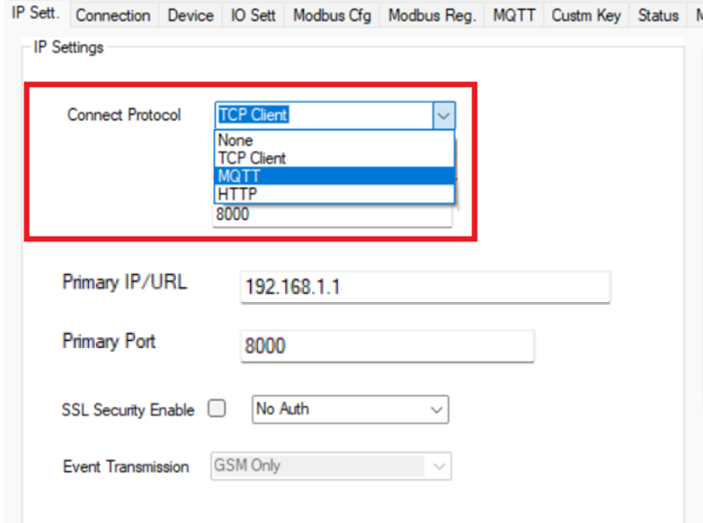
HTTP Protocol Format: In case HTTP protocol is selected in logger API Key is received in the JSON header and Modbus data is received in body with same format as of MQTT.
MQTT Settings available in supported models: https://trackso.in/how-to-setup-trackso-data-logger-for-publishing-data-over-mqtt/
Login Packet (1st Packet from Logger)
Contains basic details about logger such as mode, network, hardware version, software version
Sample
{
“msg”: “login”,
“imei”: “860987057816172”,
“model”: “WT-410M”,
“cid”: “TKSO-4G”,
“type”: “W4G LITE”,
“hwver”: “1.1”,
“swver”: “1.1.41”,
“mdbver”: “1.0”,
“time”: 1655105627,
“sig”: 23,
“tz”: “+00:00”,
“nw”: “Vodafone”
}
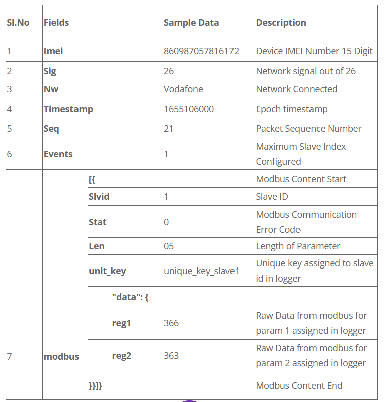
Data Event Packet Format (Modbus) depending upon different settings in the logger.(refer screenshots attached to all the types)
Type- Single Slave and Single Index Based
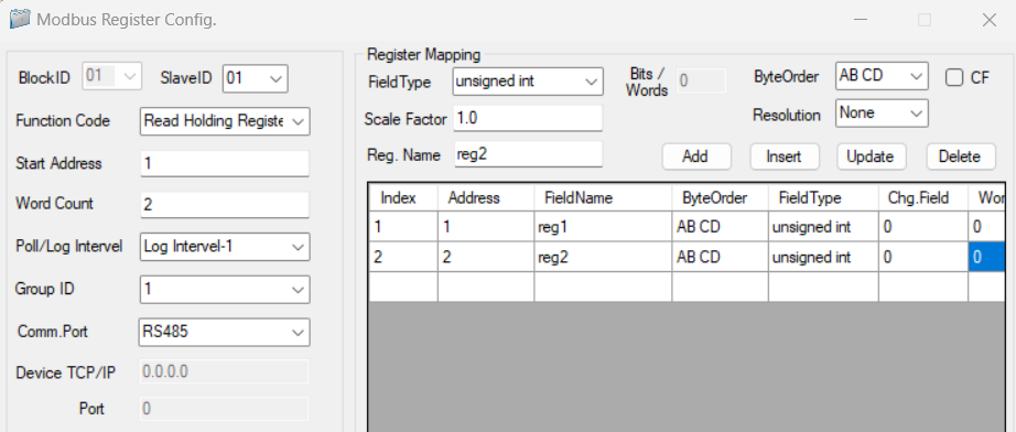
Logger Modbus Setting:

Sample Format
{
“imei”: “860987057816172”,
“sig”: 26,
“nw”: “Vodafone”,
“tz”: “+00:00”,
“seq”: 21,
“msg”: “log”,
“slave”: 1,
“logs”: 1,
“events”: [
{
“slvid”: 1,
“resptime”: 110,
“stat”: 0,
“len”: 2,
“timestamp”: 1655106000,
“unit_key”: “unique_key_slave1”,
“data”: {
“reg1”: 366,
“reg2”: 363
}
}
]
}
Tag details
Note-
- Above tag names reg1 , reg2 can be modified as per requirement.(check screenshot below)
- No. of slaves is dependent on Logger Model No.
Type- Single Slave and Multiple Index/Modbus request Based
Logger Modbus Setting:

Sample Format
{
“imei”: “860987057816172”,
“sig”: 26,
“nw”: “Vodafone”,
“tz”: “+00:00”,
“seq”: 21,
“msg”: “log”,
“slave”: 1,
“logs”: 1,
“events”: [
{
“slvid”: 1,
“resptime”: 110,
“stat”: 0,
“len”: 4,
“timestamp”: 1655106000,
“unit_key”: “unique_key_slave1”,
“data”: {
“reg1”: 366,
“reg2”: 363,
“reg3”: 36,
“reg4”: 63
}
}
]
}
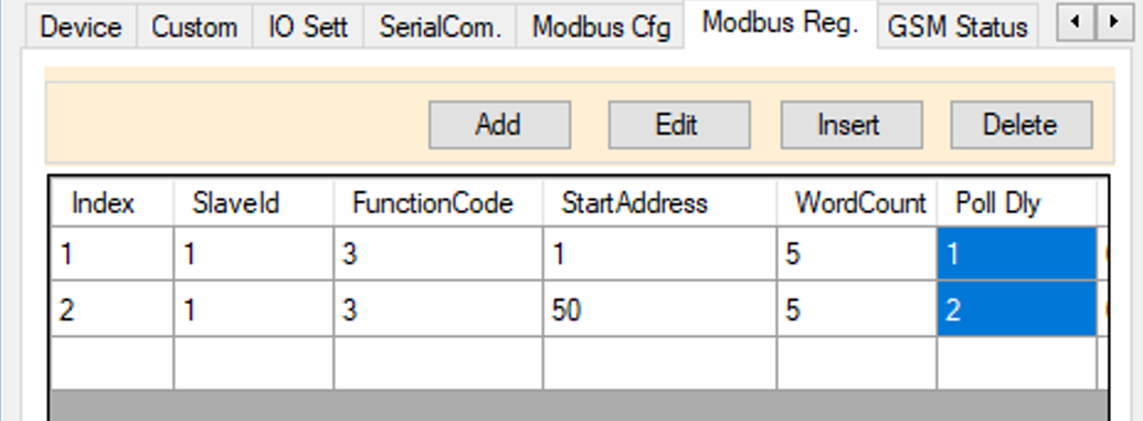
Type- Single Slave and Multiple Index Based-Different Poll Delay
This allows to sync data of two different modbus slaves at different data frequency.
Logger Modbus Setting:
Sample Format
| Index : 1: Poll Delay : 1 (Log Interval-1) | Index : 2: Poll Delay : 2 (Log Interval-2) |
| { “imei”: “860987057816172”, “sig”: 26, “nw”: “Vodafone”, “tz”: “+00:00”, “seq”: 21, “msg”: “log”, “slave”: 1, “logs”: 1, “events”: [ { “slvid”: 1, “resptime”: 110, “stat”: 0, “len”: 2, “timestamp”: 1655106000, “unit_key”: “unique_key_slave1”, “data”: { “reg1”: 366, “reg2”: 363 } } ] } |
{ “imei”: “860987057816172”, “sig”: 26, “nw”: “Vodafone”, “tz”: “+00:00”, “seq”: 21, “msg”: “log”, “slave”: 1, “logs”: 1, “events”: [ { “slvid”: 1, “resptime”: 110, “stat”: 0, “len”: 2, “timestamp”: 1655106001, “unit_key”: “unique_key_slave1”, “data”: { “reg3”: 36, “reg4”: 63 } } ] } |
In this case both the data polls will be sent in separate json.
Type- Multiple Slave and Slave ID Based Data Syncing
Logger Modbus Settings
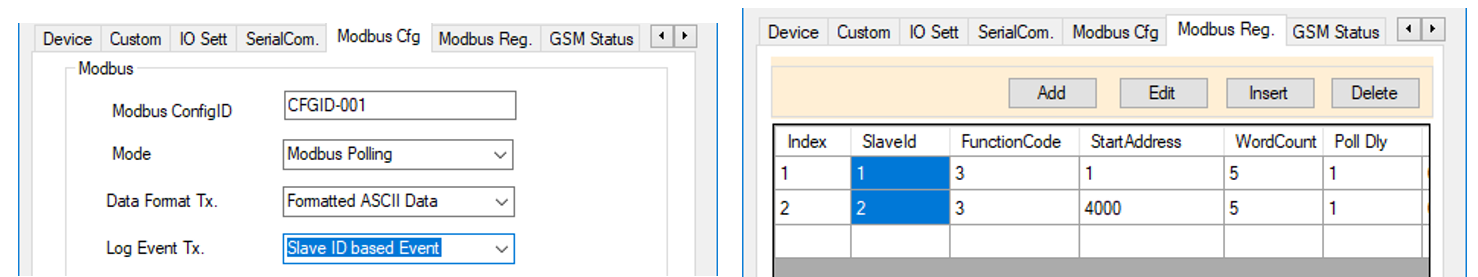
Sample Format
In this case data can be synced separately for each slave
| Slave : 1: Poll Delay : 1 (Log Interval-1) | Slave : 2: Poll Delay : 2 (Log Interval-1) |
| { “imei”: “860987057816172”, “sig”: 26, “nw”: “Vodafone”, “tz”: “+00:00”, “seq”: 21, “msg”: “log”, “slave”: 1, “logs”: 1, “events”: [ { “slvid”: 1, “resptime”: 20, “stat”: 0, “len”: 2, “timestamp”: 1655106000, “unit_key”: “unique_key_slave1”, “data”: { “reg1”: 366, “reg2”: 363 } } ] } |
{ “imei”: “860987057816172”, “sig”: 26, “nw”: “Vodafone”, “tz”: “+00:00”, “seq”: 22, “msg”: “log”, “slave”: 1, “logs”: 1, “events”: [ { “slvid”: 2, “resptime”: 10, “stat”: 0, “len”: 2, “timestamp”: 1655106001, “unit_key”: “key_2”, “data”: { “reg1”: 16, “reg2”: 23 } } ] } |
In this case data for both the slaves will be received separately on server in different json packets
Type- Multiple Slave and Combined Single Event Based
Logger Modbus Setting:

Sample Format
{
“imei”: “860987057816172”,
“sig”: 26,
“nw”: “Vodafone”,
“tz”: “+00:00”,
“seq”: 21,
“msg”: “log”,
“slave”: 2,
“logs”: 1,
“events”: [
{
“slvid”: 1,
“resptime”: 20,
“stat”: 0,
“len”: 2,
“timestamp”: 1655106000,
“unit_key”: “unique_key_slave1”,
“data”: {
“reg1”: 366,
“reg2”: 363
}
},
{
“slvid”: 2,
“resptime”: 20,
“stat”: 0,
“len”: 2,
“timestamp”: 1655106000,
“unit_key”: “key_2”,
“data”: {
“reg1”: 36,
“reg2”: 13
}
}
]
}
In this case data of multiple slaves will be combined in single request. Should be only used when total no. of param is going to be < 60
Type: IO/Analog Event Packet IO (Analog Ports)
{
“imei”: “860987054411993”,
“sig”: 31,
“nw”: “RJIO”,
“tz”: “+00:00”,
“seq”: 246,
“msg”: “log”,
“slave”: 1,
“logs”: 2,
“events”: [
{
“slvid”: 0,
“stat”: 0,
“len”: 8,
“timestamp”: 1654062240,
“unit_key”: “unit_key_2”,
“data”: {
“di1”: 0,
“di2”: 1,
“op1”: 0,
“a1”: 1.82,
“a2”: 2.47,
“s1”: 13.98,
“p1”: 0,
“sysv”: 12.39
}
}
]
}
Note-
- Above tags di , di 1 etc. all are fixed and can’t be renamed.
- Availability of Port depends on the Logger Model No.
Other Important details
This consist of other important details related to data format and other important ways of debugging.
Modbus Exception Codes
Data packet also consist of modbus exception codes for each slave which can help in easy debugging. List of codes is available here: http://trackso.in/wp-content/uploads/documents/2019/04/Modbus-Exception-Codes-TrackSo.pdf
Communication Error (Slave Not Connected, Slave Register, Serial Settings Fault)
Sample Format
{
“imei”: “860987057816172”,
“sig”: 23,
“nw”: “Vodafone”,
“tz”: “+00:00”,
“seq”: 18,
“msg”: “log”,
“slave”: 1,
“logs”: 3,
“events”: [
{
“slvid”: 10,
“resptime”: 140,
“stat”: 21,
“indx”: 1,
“len”: 0,
“timestamp”: 1655121120,
“unit_key”: “0”,
“data”: {}
}
]
}
SMS Commands (Applicable to models with SIM )
Multiple SMS Commands are available for checking logger and slave details.
Check list of commands here: – https://trackso.in/knowledge-base/sms-commands-for-trackso-data-logger/
Commands via MQTT
General command format to device read and write.
Send command from Server: $IPCFG,Command
Reply from Device: $IPCFG,P10,IMEI,Reply Status
$IPCFG is the header part of the command. Command specifies the type of command to be sent. Please Refer Device manual for detailed information on available SMS commands and same can be used over MQTT
——
Sample MQTT Command response
Command from Server: $IPCFG,<Get.ip: >
Reply from Device: $IPCFG,P10,868618057047466,<Cfg.ip: RMODE=”3″,PRI-IP=”http://http_url.com/web_Listener”,PRI-PORT=”8000″,APN=”airrtelgprs.com”,USER=””,PSWD=”” >
Command from Server: $IPCFG,<Cmd.sysrst: >
Reply from Device: $IPCFG,P10,868618057047466,Device goingto Restart;#
Command from Server: $IPCFG,<Get.io>
Reply from Device: $IPCFG,P10,868618057047466,<Cfg.io: IO-SETT=”0,60″,I-CAL=”0.00″,INP1=”INPUT-1,ON,OFF”,INP2=”INPUT-2,ON,OFF” >#
Command from Server: $IPCFG,<Stat.gsm>
Reply from Device: $IPCFG,P10,868618057047466,IMEI=868618057047466;DTM=14-06-2022 11:50:17;NW=IND airtel-R TDD LTE;SIG=21;GPRS=1:CONT;MQTT=C-OK,58;NTP=1;LOG=0#